博文
Lonsdor K518ISE/K518S Common Problems and Solutions (Newest)
Here shares the newest maintenance solutions to some common problems of Lonsdor K518ISE/K518S key programmer.
Main issues:
- Cannot connect to vehicles or cause fault codes to vehicles
- Cannot charge
- Cannot open WiFi
- Cannot connect to the adapter
- Cannot recognize chips
- Cannot detect the battery or power on automatically once the power cable is plugged in
- Appear fault code “Device Fault9FFF”, “Device Fault31” or cannot power on
- The screen gets stuck
- The screen is blurred or displays abnormally
- Buttons do not work. Cannot recognize USB or SD card
- Have no sound or have much noise
Note:
Please pay attention to the notice before using the maintenance solutions below.
1.All following solutions are for customers who can repair the K518 device on your own. Those who cannot repair the device, please do not operate by yourself.
2.Please use the original cable. Do not plug in a converted cable or the cable from other equipment. This may cause serious problems to the device that cannot be repaired.
3.Plug out the power cable and power off the device before repair.
Do not touch other components when you are changing some chip.
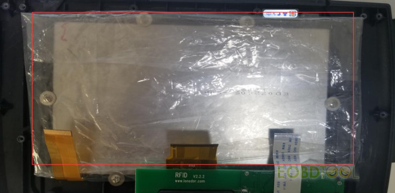
Put the motherboard in an insulated place when you are changing the touch screen. The screen cannot touch the motherboard when you are installing the screen. Otherwise it will cause a short circuit.
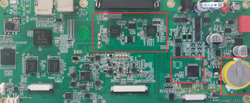
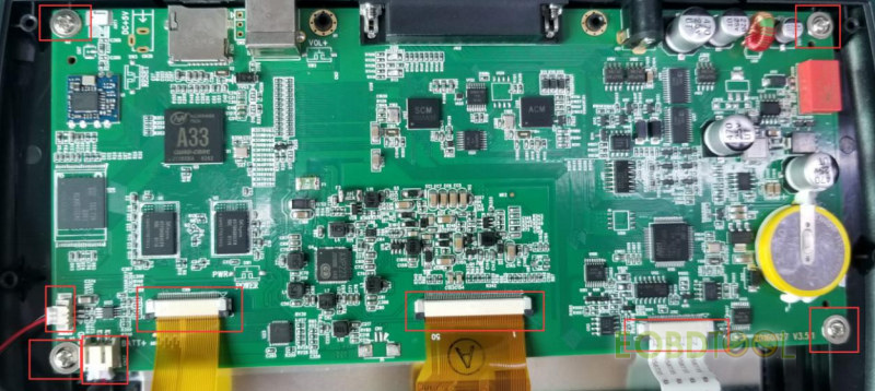
Use insulated tape to separate the motherboard, the screen and screws. Do not touch the area marked in red (showed as picture below), otherwise it will cause “fault31” or “fault9FFF”.
4.Check whether each functions of the device works well or not after repair. Check whether 12V power output is normal or not.
5.For those that cannot be repaired by solutions below, return to China for repair.
6.The solutions are for our foreign customers’ convenience. Please do not detect and study the device when repairing. Or you are responsible for a series of issues that arise. There will be accountability in serious conditions.
Problem 1: Cannot connect to vehicles or cause fault codes to vehicles
Solution:
- First power off the device and plug in the original power cable, then test the voltage of each pin of the cable.
The voltage of each pin is about 1.5V to 3.5V (except cathode and power).
If there is any pin of 5V to 12V (except power), probably there is a short circuit of some channel in the device. Remove those chips in Position U104, U105 and U103 in the picture below (marked as Position 1 and 2) and check whether the voltage is normal or not. If yes, the problem is in those chips (Position U104, U105 and U103).
If there is no voltage when testing any pin (except cathode), please check whether the OBD cable works well first.
If the cable works well, check whether there is breakdown of No. ADG1406 in Position U107 and U108 and change chips in corresponding positions.
- Chips will be burnt out due to improper operation and unstable voltage or current of vehicles. We need to alter the channel to avoid burning chips out.
Power off the device and cut off the power first, then take away the battery and the loudspeaker.
Take away screws and loosen the socket. Take out the motherboard and put it in an insulated place.
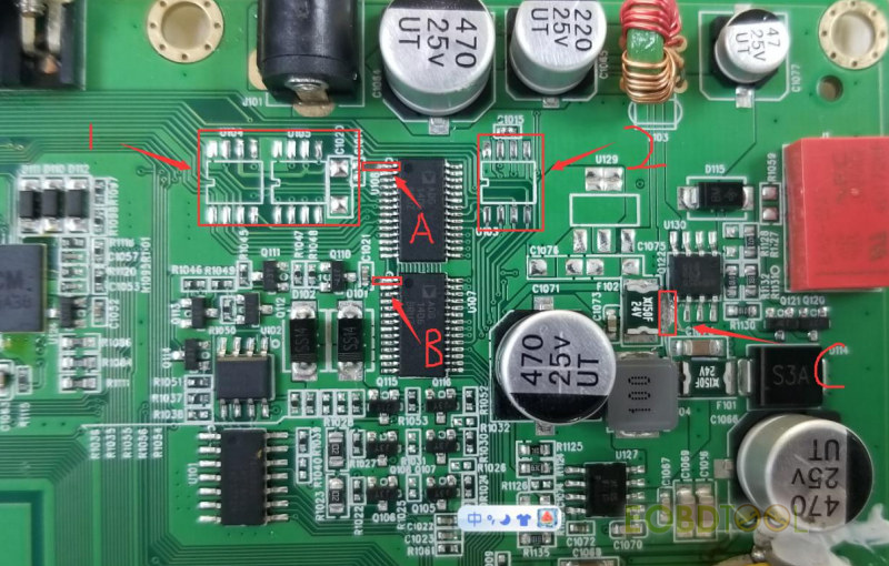
Remove chips in Position U104, U105 and U103 and capacitance (marked as Position 1 and 2).
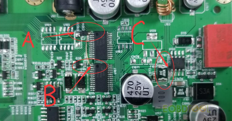
Use a blade to cut the circuit in Position A and B (the first pin from the left in Position U108 and U109). Do not cut off too much. Do not cut out off Position A and B (Do not cut the pins of the chip.).
After that, the board will show as picture below.
Weld a diode (No. 1N5819HW) in Position A. Weld the cathode of the diode to the pin of the chip. Then use an electric wire to connect the first pin of U108 and U107.
We need to cut the circuit in Position C to cut off the power of vehicles, because the power of vehicles comes straightly to this part via OBD.
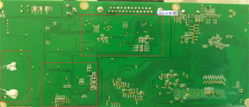
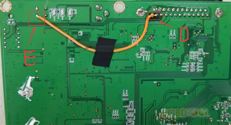
The back of the PCB board also needs to be altered. Use a soldering iron to weld Position D and E, then the power of vehicles comes through Position E.
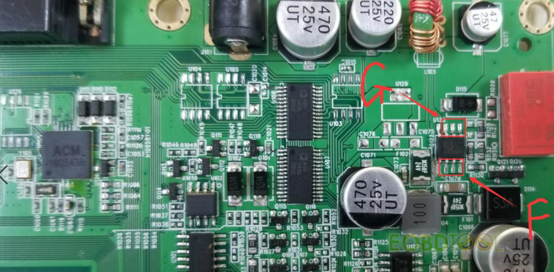
After welding, use a multimeter to check whether there is a short circuit in Position F (showed in picture below) and Position D.
If yes, the circuit is not well cut. Then use a multimeter to check whether Position G (showed in picture below) and Position D are well connected.
If not, Position D and E are not well welding; or the electric wire is broken.
After that, check whether the voltage of each outlet is normal. Do not cut other components when operating. Ask for remote guidance if you have any questions.
Problem 2: Cannot charge
Solution:
Check whether the power cable is the original cable; check whether 12V power output is normal. Check whether there is breakdown of No. FR9888 in Position U127, No. RRH050PO30 is in Position U130 and No. 150F/24-2 is in Position F102 and F101.
Problem 3: Cannot open WiFi
Solution:
Change WIFI module (No. RL-UM12BS-RTL8188EUS)
Problem 4: Cannot connect to the adapter
Solution:
Check whether the cable works well. For those which show code “31”, return to China for repair.
Problem 5: Cannot recognize chips
Solution:
Check whether the coil and the flex cable of RFID board are loose; Check if No. PCF7991AT in Position U7 and No. TMS3705A in Position U6 are broken. For those which cannot detect remotes, check whether No. MB506 in Position U5 is broken.
Problem 6: Cannot detect the battery or power on automatically once the power cable is plugged in
Solution:
Power on and off the K518 key programmer, and then charge it for two hours.
Check whether the charger can put an amount of charge into the device. If not, check whether the battery port in Position CN37 is loose or change a battery.
Problem 7: Appear fault code “Device Fault9FFF”,“Device Fault31” or cannot power on
Solution:
Return to China for repair
Problem 8: The screen gets stuck
Solution:
Insert the screen flex cable in Position CN6
Check whether No. GSL1680 in Position U25 or the touch screen is broken.
Problem 9: The screen is blurred or displays abnormally
Solution:
Change the touch screen.
Problem 10: Buttons do not work. Cannot recognize USB or SD card
Solution:
Check whether the button flex cable is loose.
For those which cannot recognize USB or SD card, check whether the slot in corresponding position is poor contact.
Problem 11: Have no sound or have much noise
Solution:
Check whether the loudspeaker cable in Position CN2 is loose;
Check whether the loudspeaker is broken.
More Lonsdor K518 key programmer problems and solutions:
Lonsdor K518 Vehicle Connection Failed Solution
Lonsdor K518S “Fault code: 6041” and “Device abn” Solution
Solution to Lonsdor K518 program Renault primastar 2004 key ok not start van
免责声明:本文中使用的图片均由博主自行发布,与本网无关,如有侵权,请联系博主进行删除。
下一篇: Which Online Functions Can Be Used after Autel MaxiIM IM508/IM608 (Pro) Tablet E
全部作者的其他最新博文
- • Lonsdor K518 Pro FCV "Update failed with exception 1 error 2" Solution
- • Padflash Read and Write Benz CRD3.10 ECU on Bench
- • How to Read and Write Mercedes CRD3.10 with PADFLASH ECU Programme via OBD ?
- • How to Clone VW POLO ID48 Chip with Launch X431 IMMO Elite and X431 Key Programm
- • How to Install & Activate PADFLASH Software on Windows 10?
- • OBDSTAR MT203 CAN Driver/Gateway Simulator User Guide
